The Pipe Feeder has emerged as an indispensable piece of equipment in modern tube and pipe processing operations, bridging the gap between raw material storage and high-speed cutting or forming machinery. This comprehensive analysis examines the fundamental role of pipe feeders in automated production lines, exploring their technological evolution, core components, and the critical advantages they bring to manufacturing efficiency. The discussion covers the two primary configurations—fully automatic and semi-automatic pipe feeders—along with their respective applications across industries ranging from automotive and aerospace to construction and renewable energy. Through detailed examination of servo motor control systems, human-machine interface operation, material handling capabilities, and integration with downstream equipment, the article demonstrates why the pipe feeder has become the essential backbone of modern tube processing operations.
1. Defining the Pipe Feeder and Its Role in Modern Manufacturing
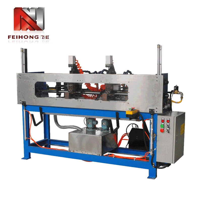
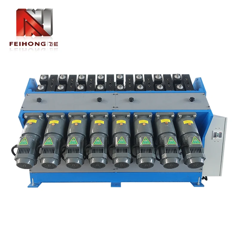
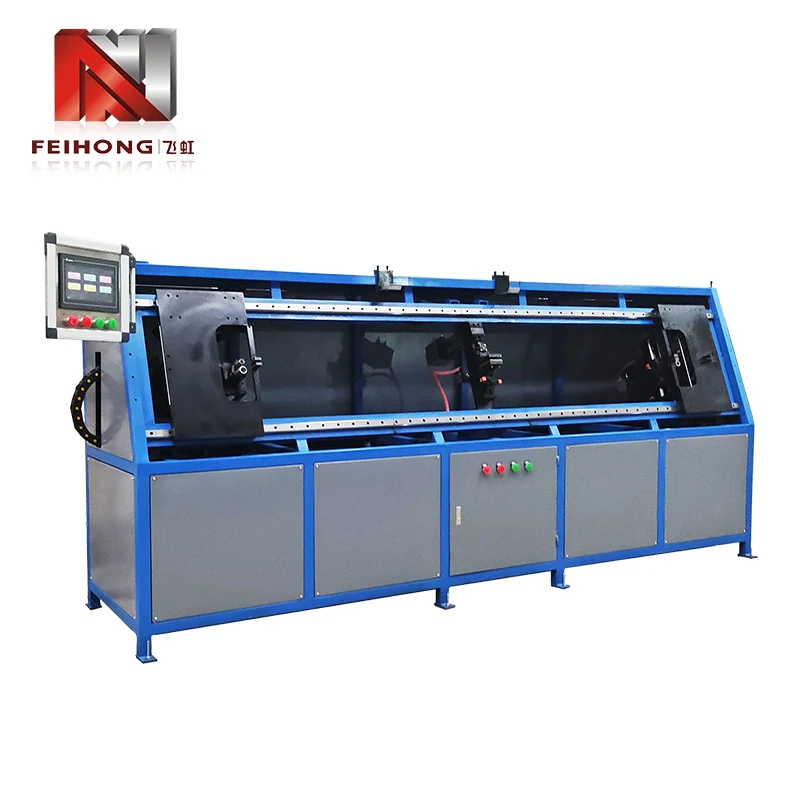
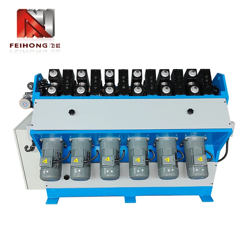
The Pipe Feeder is a specialized piece of equipment designed to automatically or semi-automatically deliver tubular materials—such as copper pipes, iron pipes, aluminum pipes, and stainless steel pipes—to downstream processing machinery including cutting machines, forming presses, and welding equipment. At its core, the pipe feeder serves as the critical interface between raw material storage and the production process, ensuring that tubes are presented to processing equipment at the correct orientation, spacing, and rate to maintain continuous, efficient production flow.
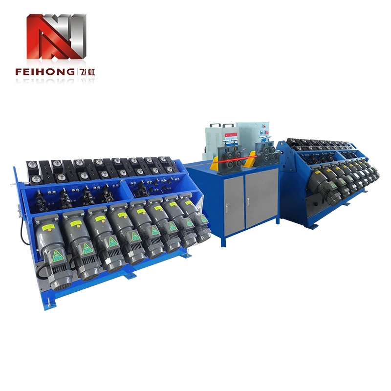
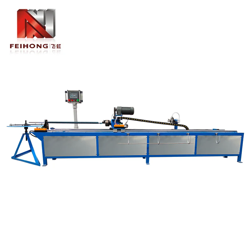
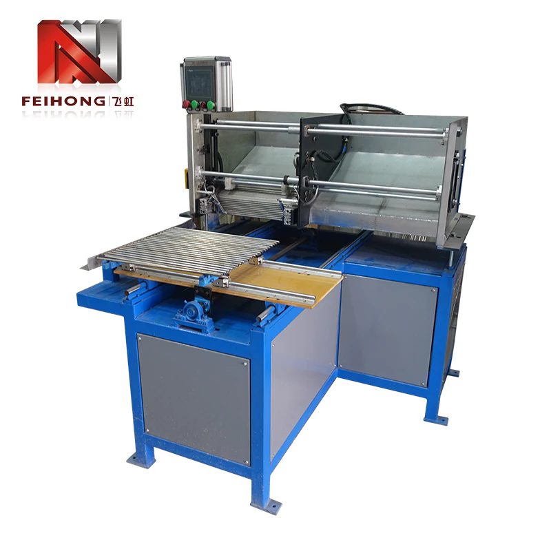
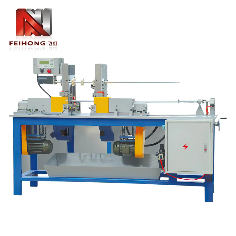
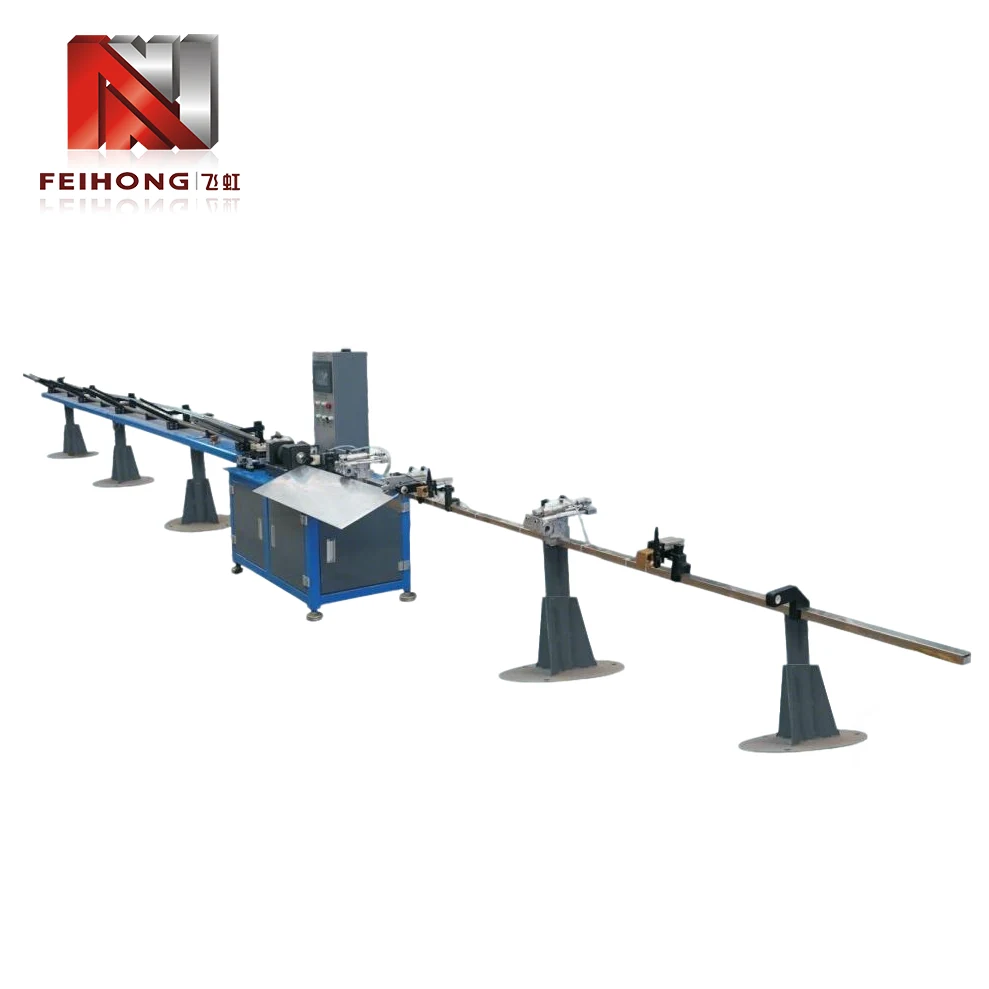 A fully automatic pipe feeder integrated with a high-speed cutting machine in a modern production environment.
In traditional manufacturing environments, pipe feeding was a manual operation: operators would pick up individual tubes, position them into the cutting or processing machine, and remove finished pieces. This approach was not only labor-intensive but also introduced significant variability in production speed and quality. The pipe feeder eliminates these inefficiencies by automating the material handling process, enabling consistent, repeatable feeding that supports high-volume production with minimal human intervention.
The significance of the pipe feeder extends beyond simple labor savings. In modern manufacturing, where just-in-time production and lean manufacturing principles dominate, the ability to maintain a steady, uninterrupted flow of material to processing equipment is essential for achieving optimal throughput. The pipe feeder achieves this through a combination of mechanical precision, electronic control, and intelligent sensing, making it a cornerstone of automated tube processing lines across multiple industries.
2. The Technological Evolution of Pipe Feeding Equipment
The journey from manual pipe handling to today's sophisticated pipe feeders reflects the broader trajectory of industrial automation. Understanding this evolution provides essential context for appreciating the capabilities of modern pipe feeding systems.
2.1 The Era of Manual Pipe Handling
In the early days of tube and pipe processing, all material handling was performed manually. Workers would retrieve individual pipes from storage racks, carry them to cutting or forming machines, and manually feed them into the processing equipment. This approach was inherently limited by human factors: fatigue, inconsistency, and the inability to maintain a steady feed rate over long shifts. Moreover, manual handling posed significant safety risks, particularly when working with heavy or sharp-edged tubes.
2.2 The Introduction of Mechanized Feed Systems
The first mechanized feed systems appeared in the mid-20th century, typically using simple roller conveyors or chain-driven mechanisms to move pipes along a production line. These early systems reduced some manual effort but still required operator intervention for loading and positioning. They lacked precise control over feed length and timing, limiting their effectiveness for high-precision applications.
2.3 The Rise of Computer-Controlled Pipe Feeders
With the advent of programmable logic controllers (PLCs) and servo motor technology in the 1980s and 1990s, pipe feeders underwent a dramatic transformation. Computer-controlled systems could precisely regulate feed length, speed, and acceleration, enabling consistent placement of tubes for cutting or forming operations. The integration of human-machine interfaces (HMIs) allowed operators to easily set parameters and monitor performance, reducing setup time and improving overall equipment effectiveness.
2.4 The Modern Pipe Feeder: Intelligence and Connectivity
Today's pipe feeders are highly sophisticated devices that incorporate sensors, data logging, and communication protocols for integration with factory-wide automation systems. Modern pipe feeders can automatically adjust to variations in tube diameter, wall thickness, and material composition, ensuring optimal feeding performance under changing conditions. They also feature predictive maintenance capabilities, alerting operators to potential issues before they cause downtime.
This evolution has established the pipe feeder as a critical enabler of advanced manufacturing, allowing companies to achieve higher production rates, improved quality, and greater flexibility in responding to customer demands.
3. Core Components and Operating Principles
Understanding the internal architecture of a pipe feeder is essential for selecting the right equipment for a given application and for effective maintenance and troubleshooting. While designs vary among manufacturers, most pipe feeders share a common set of core components.
3.1 Loading Mechanism
The loading mechanism is responsible for receiving raw tubes from a storage rack or conveyor and presenting them to the feeding system. Depending on the design, loading can be manual, semi-automatic, or fully automatic. Automatic loading systems often use a lifting device that raises a bundle of tubes and allows them to roll individually onto a feed track.
3.2 Feed Drive System
The feed drive system moves the tube forward to the processing station. This typically involves a set of powered rollers or a pinch-roll arrangement driven by a servo motor. The servo motor provides precise control over feed speed and length, allowing the pipe feeder to accommodate varying tube diameters and processing requirements.
3.3 Guiding and Alignment Components
To ensure that the tube enters the processing machine correctly, the pipe feeder incorporates guiding rollers, side alignment plates, and straightening devices. These components prevent skewing, bending, or misalignment that could lead to processing defects.
3.4 Control System
Modern pipe feeders are equipped with a programmable logic controller (PLC) and a user-friendly HMI touchscreen. The control system manages feed parameters, monitors sensors, and communicates with upstream and downstream equipment. Many systems also include remote monitoring capabilities for centralized production management.
3.5 Sensors and Feedback Devices
A range of sensors—including proximity switches, photoelectric sensors, and encoders—provide real-time feedback on tube position, feed length, and system status. This feedback enables closed-loop control, ensuring consistent feeding accuracy and early detection of anomalies.
Together, these components form a robust system that can handle a wide variety of tube sizes and materials while maintaining high levels of precision and reliability.
4. Fully Automatic vs. Semi-Automatic Pipe Feeders
Pipe feeders are broadly categorized into two types: fully automatic and semi-automatic. The choice between these configurations depends on production volume, labor availability, and budget considerations.
4.1 Fully Automatic Pipe Feeders
Fully automatic pipe feeders require minimal operator intervention. They feature automatic loading from a magazine or bundle, continuous feeding of individual tubes, and automatic ejection of finished pieces. These systems are ideal for high-volume production environments where consistency and speed are paramount. The operator's role is limited to monitoring the system, adjusting parameters via the HMI, and replenishing the raw material supply.
Advanced fully automatic feeders can also integrate with downstream equipment such as chamfering machines, threading units, and welding stations, creating a fully automated production cell.
4.2 Semi-Automatic Pipe Feeders
Semi-automatic pipe feeders require an operator to load each tube manually into the feed mechanism. The feeder then takes over the precise positioning and advancement of the tube to the processing station. This type of feeder is suitable for lower-volume production or for applications where tubes come in varying lengths or sizes that are difficult to automate. Semi-automatic feeders are typically more affordable and easier to maintain than fully automatic units.
4.3 Comparison of Capabilities
The following table summarizes the key differences between the two types:
| Feature | Fully Automatic | Semi-Automatic |
|---|---|---|
| Loading method | Automatic from magazine/bundle | Manual operator loading |
| Operator involvement | Minimal (monitoring only) | Requires regular loading |
| Production speed | High, continuous | Moderate, depends on operator |
| Flexibility for different tube sizes | Good (with adjustment) | Excellent (manual changeover) |
| Typical application | Mass production, automotive, HVAC | Job shops, custom fabrication |
| Capital cost | Higher | Lower |
Both types have their place in modern manufacturing, and the decision often depends on a careful analysis of production requirements and return on operational efficiency.
5. Material Compatibility and Application Scope
The Pipe Feeder is designed to handle a broad spectrum of tubular materials, making it versatile across multiple industries.
5.1 Material Types
Pipe feeders are commonly used with:
- Copper pipes: Used in HVAC, plumbing, and refrigeration systems
- Steel pipes (carbon, stainless, galvanized): Used in construction, automotive exhaust systems, and structural applications
- Aluminum pipes: Used in aerospace, automotive heat exchangers, and lightweight structures
- Plastic and composite tubes: Used in chemical processing and telecommunications
- Alloy pipes: Used in high-temperature and high-pressure applications
The pipe feeder must be equipped with appropriate gripping and guiding components to accommodate the surface finish, hardness, and weight of the specific material being processed.
5.2 Tube Diameter and Length Ranges
Modern pipe feeders are available in a variety of sizes, with capabilities ranging from small-diameter tubing (6 mm) to large-diameter pipes (up to 150 mm or more). The feed length is also adjustable, with some systems capable of feeding lengths exceeding 10 meters.
5.3 Key Application Industries
The versatility of pipe feeders makes them essential in the following sectors:
- Automotive: Production of exhaust pipes, brake lines, fuel lines, and structural tubes
- HVAC and Refrigeration: Manufacturing of heat exchangers, condenser coils, and refrigerant lines
- Construction and Infrastructure: Fabrication of scaffolding, handrails, and structural supports
- Aerospace: Production of hydraulic tubes, fuel lines, and structural components
- Renewable Energy: Manufacturing of solar panel frames, wind turbine structural parts, and geothermal piping
Each industry places specific demands on the pipe feeder, such as high-speed operation for automotive lines or extreme precision for aerospace applications. The modular design of modern pipe feeders allows them to be customized for these varying requirements.
6. Integration with Cutting and Forming Systems
A pipe feeder rarely operates in isolation; it is typically part of a production line that includes cutting, forming, chamfering, or welding equipment. Proper integration is crucial for achieving seamless material flow and maximizing overall productivity.
6.1 Synchronization with Cutting Machines
In a typical cutting line, the pipe feeder advances the tube to a predetermined length, then pauses while a cutting machine—often a high-speed circular saw or laser cutter—performs the cut. The feeder then advances the next segment. This synchronous operation requires precise communication between the feeder controller and the cutting machine's control system, often via a fieldbus interface such as Profinet or EtherCAT.
6.2 Coordination with Forming and End-Finishing Equipment
For applications requiring pipe bending, flaring, or threading, the pipe feeder must deliver the tube to the forming station in the correct orientation and at the right timing. Advanced systems incorporate servo-controlled positioning that can rotate the tube to a specific angle before it enters the forming die, enabling complex multi-step operations.
6.3 Integration with Stackers and Conveyors
After processing, the finished tubes are typically removed by a stacker or conveyor system. The pipe feeder's control system can coordinate with these downstream devices to ensure smooth handoff and prevent bottlenecks.
6.4 Role of the Human-Machine Interface (HMI)
The HMI serves as the central point for setting up and monitoring the entire integrated system. Operators can input desired cut lengths, feed speeds, and other parameters, and the HMI displays real-time status, alarms, and production counts. Modern HMIs often include touch-screen interfaces and intuitive graphics, simplifying operation and reducing the learning curve for new operators.
7. Maintenance, Reliability, and Operational Considerations
To ensure long service life and consistent performance, regular maintenance of the pipe feeder is essential. The following practices are recommended:
7.1 Preventive Maintenance Schedule
A structured preventive maintenance program should include:
- Daily checks: Inspect roller condition, check for unusual noise or vibration, and verify HMI readings
- Weekly maintenance: Lubricate moving parts, clean sensors, and verify alignment of guiding components
- Monthly inspections: Check belt or chain tension, test emergency stop functions, and review alarm history
- Quarterly servicing: Perform in-depth inspection of servo motors, gearboxes, and control system connections
- Annual overhaul: Replace wear parts such as rollers, bearings, and drive belts, and recalibrate feedback devices
7.2 Common Issues and Troubleshooting
Some typical operational issues include:
- Inconsistent feed length: Often caused by encoder misalignment, roller slippage, or worn drive components
- Tube surface marks: Resulting from dirty or damaged guiding rollers
- Misalignment of tube entering the processing machine: Usually due to worn guides or improper adjustment
- Communication errors between feeder and cutting machine: Typically resolved by checking cables and PLC program parameters
7.3 Safety Features
Modern pipe feeders are equipped with multiple safety features, including light curtains, emergency stop buttons, and safety interlocks that prevent operation when guards are open. Proper training on these safety systems is essential for all operators.
7.4 Maximizing Up-time and Reliability
To maximize reliability, manufacturers recommend using genuine replacement parts, keeping a stock of critical spares, and maintaining a clean work environment. Additionally, software updates provided by the equipment manufacturer can improve performance and add new functionality.
8. Frequently Asked Questions
While both devices feed material to processing machines, a pipe feeder is specifically designed for tubular materials (hollow sections) and typically includes guiding and support features that prevent deformation. A bar feeder is used for solid round bars, often in turning operations.
Some advanced pipe feeders feature quick-adjust mechanisms and programmable parameters that allow for rapid changeover between sizes. However, most systems require some manual adjustment of guiding components and feed settings when switching tube diameters.
Servo-driven pipe feeders typically achieve feed length accuracy within ±0.2 mm, depending on the quality of the encoder and the mechanical condition of the feed mechanism. High-end systems can achieve ±0.05 mm for precision applications.
With proper maintenance, a pipe feeder can operate reliably for 15 to 20 years or more. Key wear components such as rollers, drive belts, and bearings may need replacement at intervals of 2 to 5 years, depending on the operating cycle.
Yes, even fully automatic systems require trained operators to set parameters, perform routine inspections, and troubleshoot minor issues. However, the training is typically less intensive than for manual feeding operations, and modern HMIs make the system user-friendly.
Zhaoqing Feihong Machinery & Electrical Co., Ltd. is a trusted manufacturer of pipe feeders and tube processing equipment, delivering innovative solutions to customers worldwide. To explore how our pipe feeders can improve your production efficiency, contact us for expert consultation and customized system design.
Get in Touch