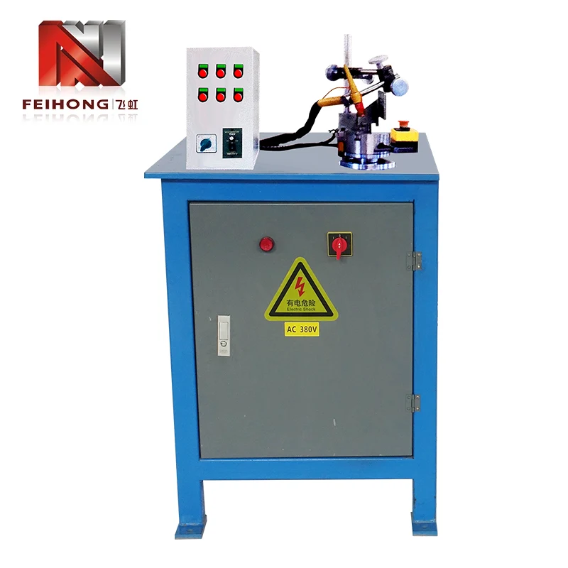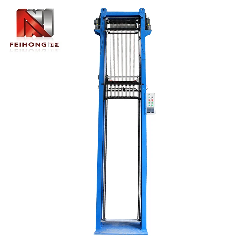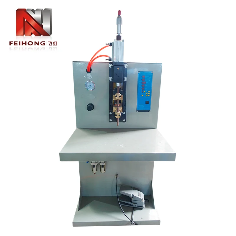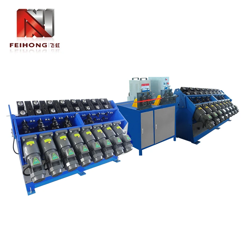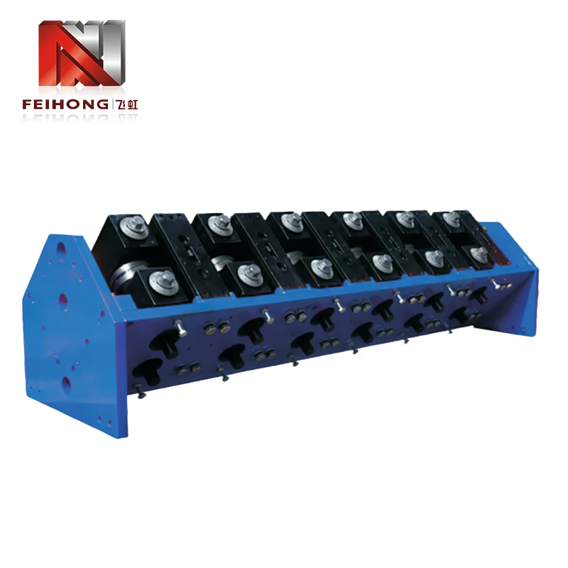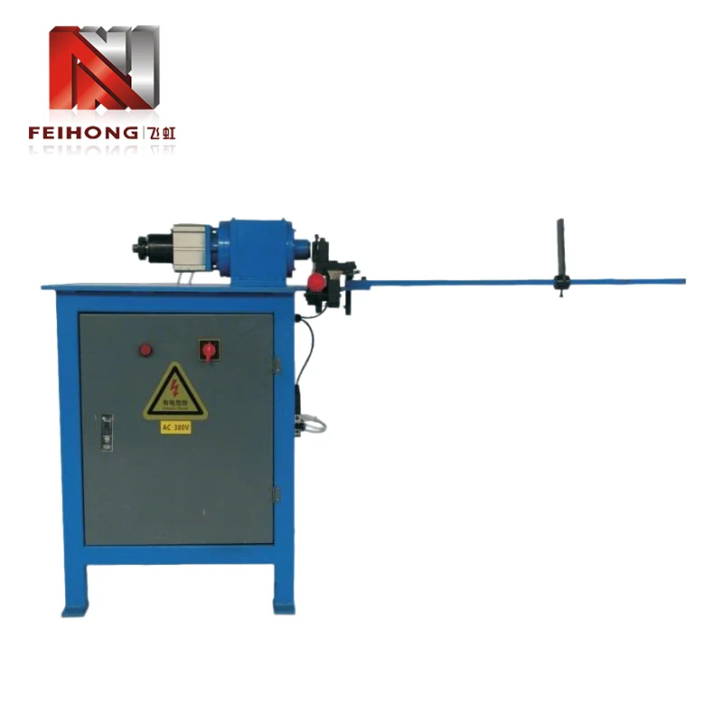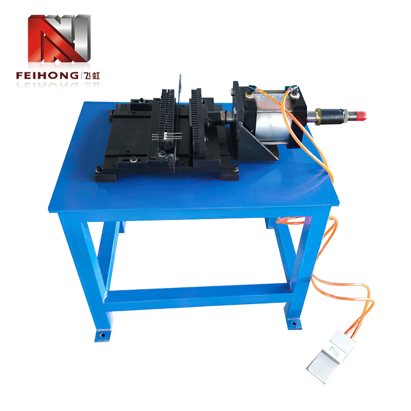
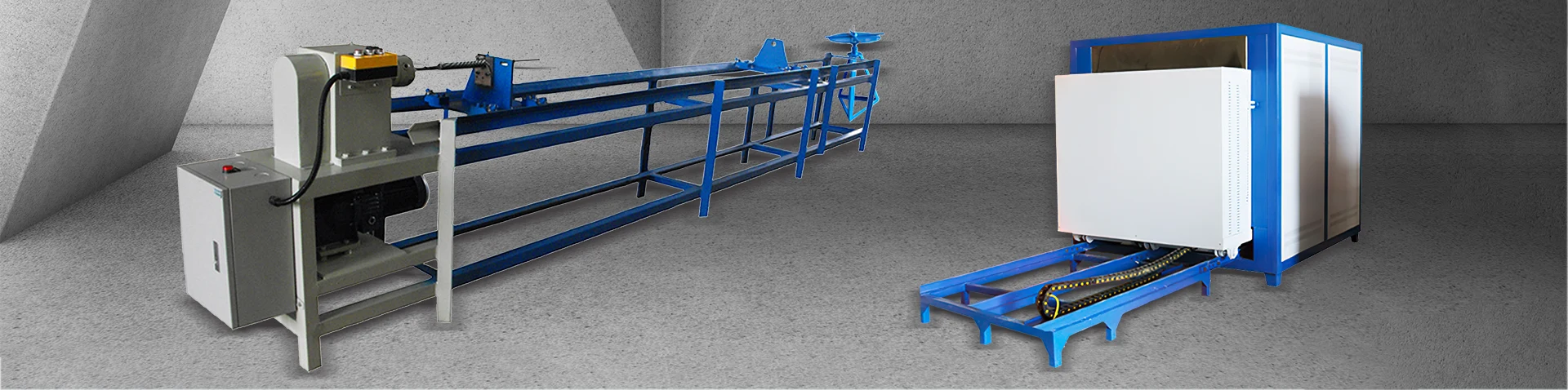
The Flat Pipe Bender stands as a cornerstone in modern metal forming, enabling precise bending of rectangular and oval tubing across automotive, construction, and HVAC industries. This article examines the working principles, key types, material behaviours, and selection criteria for flat pipe bending equipment. It also covers maintenance best practices, common failure modes, and emerging technologies that shape the future of profile bending. Engineered for durability and repeatability, the flat pipe bender delivers consistent results even with high-strength alloys. Whether for prototypes or high-volume production, understanding the capabilities and limitations of this equipment ensures optimal fabrication outcomes.
1. What Exactly Is a Flat Pipe Bender and How Does It Work?
A Flat Pipe Bender is a specialized machine designed to bend rectangular, square, or oval tubes along a single plane without collapsing the cross‑section. Unlike round pipe benders that use mandrels and wiper dies to maintain circular profiles, flat pipe bending requires carefully matched tooling that supports the broader faces of the tube while allowing the narrower edges to deform controllably. The fundamental challenge lies in managing the differential stretching and compression that occur across the width of a flat section—the outer wall elongates while the inner wall compresses, and without proper support, the tube will buckle or wrinkle.
The working principle centres on three main elements: the bending die (or form), the clamp die, and the pressure die. The tube is secured between the clamp and bending dies, then rotated around the bending die's radius. For flat profiles, the bending die incorporates a groove that matches the tube's external dimensions, providing lateral support to prevent the wider faces from collapsing inward. Some advanced machines also employ a wiper die that slides along the tube's inner radius to eliminate wrinkling, and a mandrel (though less common for flat sections) can be inserted to support the internal cavity if the tube is hollow. The entire process is typically hydraulically or electrically actuated, with CNC controls enabling precise angle repeatability and multi‑step bending sequences.
One of the defining characteristics of a Flat Pipe Bender is its ability to produce bends with minimal distortion while maintaining tight tolerances. This is achieved through controlled springback compensation—the machine over‑bends slightly beyond the target angle, knowing that the material will relax back by a predictable amount. Modern units integrate sensors that measure actual bend angles in real time and adjust the ram position dynamically, ensuring that each part matches the CAD model within ±0.5 degrees. The combination of robust construction and intelligent control makes this equipment indispensable for high‑quality fabrication.

2. Which Industries Rely Most Heavily on Flat Pipe Bending?
Flat pipe bending is not a niche process—it is embedded in the supply chains of multiple heavy industries. The following sectors depend on Flat Pipe Bender equipment to produce structural and aesthetic components that cannot be achieved with round tubing.
- Automotive & Transportation: Chassis frames, roll cages, seat structures, and exhaust system components often use rectangular or oval tubing. Flat bending allows designers to maximise strength‑to‑weight ratios while packaging components efficiently within tight vehicle envelopes.
- Construction & Architecture: Handrails, staircases, curtain wall mullions, and decorative metal facades frequently feature bent rectangular sections. The visual appeal of clean, wrinkle‑free bends is paramount in architectural applications.
- HVAC & Ventilation: Ductwork and air‑handling systems use flat‑oval tubes to maintain high airflow while fitting into shallow ceiling spaces. Bending these profiles requires precise control to avoid restricting the internal cross‑section.
- Agricultural Equipment: Tractor roll‑over protection structures (ROPS), implement frames, and irrigation pivots all utilise bent rectangular tubing for durability and cost‑effective manufacturing.
- Furniture & Office Interiors: Modern desk frames, shelving systems, and exhibition stands exploit the clean lines of bent flat tubing to achieve minimalist aesthetics with high structural integrity.
In each of these fields, the flat pipe bender serves as an enabler of design freedom, allowing engineers to replace welded joints with continuous bent sections that are stronger, lighter, and more visually appealing. The versatility of the equipment means that even small‑scale workshops can produce professional‑grade components for these demanding markets.
3. What Are the Main Types of Flat Pipe Benders Available Today?
Flat pipe bending machines are categorised by their actuation method, control system, and tooling configuration. Choosing the right type depends on production volume, material type, and bend complexity. Below is a comparative overview of the most common variants.
| Type | Actuation | Typical Capacity | Best Suited For |
|---|---|---|---|
| Manual | Lever / hand pump | Up to 50 mm width | Prototypes, maintenance, small batches |
| Hydraulic | Hydraulic cylinder | Up to 150 mm width | Medium‑volume production, thick walls |
| CNC Rotary Draw | Servo‑electric / hybrid | Up to 200 mm width | High‑volume, tight tolerances, complex shapes |
| Compression Bender | Pneumatic or hydraulic | Up to 100 mm width | Simple bends, HVAC ducts, low cost |
Manual benders are favoured by maintenance departments and educational institutions because of their low cost and simplicity. Hydraulic machines offer a good balance of power and affordability, making them the workhorse of many fabrication shops. CNC rotary draw benders represent the state‑of‑the‑art, with the ability to store hundreds of programs and automatically compensate for material variations. Compression benders, while less precise, are extremely fast and economical for mass‑producing simple bends in thin‑walled tubes.
Beyond these four categories, there are also hybrid machines that combine hydraulic power with CNC control, offering the best of both worlds. When selecting a type, it is essential to consider not only the current workload but also the potential for future expansion into more complex geometries.
4. How Does Material Selection Affect the Bending Process?
The material of the tube is arguably the most critical factor influencing bend quality. Different alloys exhibit varying degrees of ductility, springback, and work hardening, all of which must be accounted for in the bending setup. Below is a breakdown of common materials and their bending characteristics.
- Mild Steel
- Most forgiving material; offers good ductility and predictable springback. Suitable for most general‑purpose bending operations without special precautions.
- High‑Strength Low‑Alloy (HSLA) Steel
- Requires higher bending forces and exhibits greater springback. CNC compensation is strongly recommended to maintain angle accuracy.
- Stainless Steel (Austenitic)
- Work‑hardens rapidly, which can lead to cracking if the bend radius is too tight. Use slower ram speeds, adequate lubrication, and polished tooling to reduce friction.
- Aluminium Alloys (5xxx, 6xxx)
- Lightweight and corrosion‑resistant, but prone to wrinkling and cracking. Larger bend radii (3‑5× tube width) and careful clearance settings are essential.
- Copper & Brass
- Highly ductile and easy to bend, but soft surfaces are easily marred. Fine‑finished dies and proper clearance prevent galling and surface defects.
In addition to the alloy, the wall thickness plays a vital role. Thicker walls provide greater resistance to collapse but demand higher tonnage. Thin‑wall tubes are susceptible to buckling on the inner radius and may require internal mandrels or specialised wiper dies. A general rule of thumb is that the wall thickness should be at least 5% of the tube width to achieve reliable bending without internal support.
5. What Key Specifications Should You Evaluate When Choosing a Flat Pipe Bender?
Selecting the right machine involves more than just matching the maximum tube size. A comprehensive evaluation should cover the following parameters, each of which directly impacts performance and longevity.
- Maximum Bending Capacity: This includes the tube width, height, and wall thickness that the machine can handle. Always choose a machine with at least 20% higher capacity than your largest expected part to account for material variations and unforeseen demands.
- Minimum Bend Radius: Expressed as a multiple of the tube width (e.g., 2×W). Tighter radii require more sophisticated tooling and higher machine rigidity. For most applications, a radius of 3×W is a safe starting point.
- Bending Angle Range: Most machines can bend from 0° to 180°, but some specialised units offer up to 220° for over‑bending applications. Ensure the machine can achieve the angles you need without tooling interference.
- Cycle Speed: Measured in seconds per bend, this affects production throughput. Hydraulic machines typically cycle in 5‑15 seconds, while servo‑electric units can achieve 2‑5 seconds for small sections.
- Control System: Basic PLC vs. full CNC with touchscreen programming. CNC offers greater flexibility but comes with a higher initial cost and steeper learning curve.
- Tooling Compatibility: Check whether the machine uses industry‑standard tooling or proprietary designs. Standardised tooling reduces lead times and costs for replacement dies.
- Power Requirements: Hydraulic machines need a dedicated power unit (often 15‑75 kW), while electric machines run on standard 3‑phase supplies. Consider your facility's electrical infrastructure.
A well‑chosen machine will not only meet current production needs but also accommodate future growth in part complexity and material diversity. It is wise to involve both production engineers and maintenance staff in the selection process to ensure that the chosen equipment aligns with operational realities.
6. What Are the Most Common Flat Pipe Bending Defects and How Can They Be Prevented?
Even with a high‑quality flat pipe bender, defects can arise from improper setup, worn tooling, or material inconsistencies. Understanding these failure modes is the first step toward prevention. Below are the most frequently encountered issues and their remedies.
- Wrinkling on the Inner Radius: Occurs when the inner wall compresses faster than the material can accommodate. Caused by insufficient wiper die pressure or a bend radius that is too tight for the wall thickness. Prevention: Increase wiper die force, use a larger radius, or add a mandrel to support the inner wall.
- Cross‑Sectional Collapse (Flattening): The wide faces of the tube cave inward, losing structural integrity. Common with thin‑wall tubes or when the bending die does not provide adequate lateral support. Prevention: Use a die with a closer fit to the tube's external dimensions, and consider a pressure die that actively pushes against the outer wall during bending.
- Springback Variation: Inconsistent springback leads to parts that do not meet the target angle, especially when bending high‑strength steels or aluminium. Prevention: Implement CNC over‑bending with real‑time angle feedback. Also, ensure that the material is from a single batch with consistent mechanical properties.
- Surface Scratches and Galling: Scratches occur when the tube slides against the bending die or wiper. Galling is particularly problematic with aluminium and stainless steel. Prevention: Use polished tooling, apply appropriate lubricant, and maintain proper clearance to reduce friction.
- Twisting or Spring‑Back in the Plane: The tube may rotate slightly out of the bending plane, resulting in a twisted part. This is often due to uneven clamping pressure or misaligned tooling. Prevention: Check clamp die alignment and ensure that the tube is seated squarely before each bend.
Regular inspection of tooling and periodic calibration of the machine's angle sensors can catch many of these issues before they result in scrapped parts. Documenting the parameters for each successful setup also helps in troubleshooting future runs.
7. How Should a Flat Pipe Bender Be Maintained for Long‑Term Reliability?
Proper maintenance is essential to preserve the accuracy and lifespan of a flat pipe bender. A proactive regimen not only reduces downtime but also ensures consistent bend quality. The following step‑by‑step approach is recommended for most hydraulic and CNC machines.
- Daily visual inspection: Check for hydraulic fluid leaks, loose bolts, and signs of wear on the clamping and bending dies. Clean the work area and remove any metal chips or debris.
- Lubrication of moving parts: Apply the manufacturer‑specified grease or oil to all pivot points, slideways, and the bending die spindle. Over‑greasing can attract dirt, so use only the recommended amount.
- Hydraulic fluid maintenance: Monitor fluid levels and change the filter at the intervals specified in the manual. Contaminated fluid is a leading cause of valve and pump failure.
- Calibration of angle sensors: Use a precision protractor or digital angle gauge to verify the machine's bend angle accuracy. Recalibrate if deviations exceed ±0.3°.
- Inspection of wiper and pressure dies: Check for scoring or deformation. Worn dies should be reground or replaced to prevent wrinkling and surface damage.
- Electrical system check: For CNC machines, verify that all cables are secure, emergency stops function correctly, and the control panel displays no error codes.
- Annual comprehensive service: Engage a certified technician to perform a full overhaul, including hydraulic cylinder seals, pump wear, and software updates.
Keeping a detailed log of all maintenance activities—including oil changes, die replacements, and calibrations—helps in predicting wear patterns and scheduling downtime efficiently. A well‑maintained flat pipe bender can deliver decades of reliable service.
8. What Does the Future Hold for Flat Pipe Bending Technology?
The evolution of flat pipe bending is driven by the demand for greater efficiency, precision, and sustainability. Industry 4.0 concepts are increasingly being integrated into bending machines, enabling real‑time data collection and predictive maintenance. Sensors embedded in the tooling monitor wear and force variations, feeding information back to a central system that can recommend optimal bending parameters automatically.
Another emerging trend is the use of servo‑electric drives instead of traditional hydraulics. These systems consume less energy, produce less noise, and offer higher positioning accuracy. They are particularly attractive for manufacturers aiming to reduce their carbon footprint. Additionally, additive manufacturing is beginning to influence tooling design—3D‑printed dies with conformal cooling channels can improve thermal management during high‑speed bending.
Artificial intelligence is also making its way into bend sequencing. AI algorithms can analyse the material properties and history of each tube batch to predict springback with unprecedented accuracy, reducing scrap rates and setup time. Furthermore, collaborative robots (cobots) are being paired with flat pipe benders to automate loading and unloading, allowing human operators to focus on quality control and process optimisation.
As the industry moves towards digital twins—virtual replicas of the physical bending cell—engineers will be able to simulate entire production runs before a single tube is bent. This capability will dramatically shorten the time from design to finished part, making custom fabrication almost as efficient as mass production. The future of flat pipe bending is undoubtedly smart, connected, and increasingly autonomous.
9. Frequently Asked Questions About Flat Pipe Benders
A flat pipe bender is specifically designed for rectangular, square, or oval profiles, using tooling that supports the wider faces to prevent collapse. A round pipe bender works with circular tubes and typically employs mandrels to maintain the internal diameter. The tooling and bending mechanics are fundamentally different, so the two machines are not interchangeable.
Yes, but it requires careful preparation. Use polished dies, apply a suitable lubricant (e.g., chlorinated or synthetic drawing oil), and ensure that the wiper die is in excellent condition. Slower bending speeds also reduce the risk of galling and surface scratching.
Most manufacturers recommend changing the hydraulic fluid every 2,000 operating hours or annually, whichever comes first. However, the interval depends on the oil quality, operating temperature, and contamination levels. Regular oil analysis can help determine the optimal change schedule for your specific conditions.
Yes, but the minimum radius is limited by the tube's width, wall thickness, and material ductility. For most materials, a radius of 3× the tube width is achievable without special tooling. For tighter radii (e.g., 1.5×W), you will need a mandrel and a wiper die, and the machine must have sufficient rigidity to handle the increased forces.
Always wear appropriate personal protective equipment (gloves, safety glasses, and hearing protection). Never place hands near the bending area during operation. Ensure that emergency stop buttons are accessible and that the machine is properly guarded. Regular training and clear operating procedures are essential to prevent accidents.
Ready to optimise your tube bending operations? Our team at Zhaoqing Feihong Machinery & Electrical Co., Ltd. has extensive experience in flat pipe bending solutions. Whether you need a new machine, spare tooling, or technical advice, we are here to help.
Contact us today to discuss your specific requirements and discover how our expertise can enhance your production efficiency.
Get in Touch Now